CAD Data Files or Prints? Each has Advantages.
CAD files have definitely made the CNC machining industry run smoothly. Their ability to provide complex geometry from the CAD engineer provides more accurate parts and simplifies the programming of complex parts. But as with all manufacturing process methods, there are advantages and disadvantages that program managers, engineers, machinists and inspectors should be aware of.
Advantages of working with CAD Files
• Fast and accurate programming of CAM and CMM inspection equipment
• Increased programming accuracy from data coming directly from the design engineer
• The ability to measure parts using a Profiles of a Line, or Surface GD&T
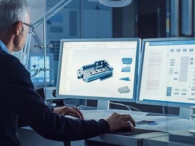
• Allows for visualizing the part in 3D. Prints are sometimes weak at confirming small features and features that are Blind vs Through. Being able to visualize the part is critical to manufacturing and is very helpful when designing custom tooling used to hold and manufacture the part
• When “Print only” is provided, typically the part is drawn. The concern is always if the print was interpreted correctly when it was redrawn. It is sometimes hard to check since we are not the original designer and cannot confirm design intent. When this occurs, we request that the customer confirm our drawing for accuracy.
Advantages of working with Prints
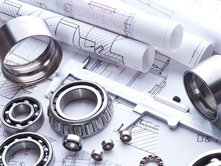
• Prints provide a paper record that is easier to control, with revision and date stamps at time of printing
• CAD Data has no- or limited-tolerances for part features
• CAD files may not match the print dimensions. This is typically seen when bilateral tolerancing or nominal tolerance is used. An example of Bilateral Tolerance is 1.002″ +/-0.003″ (Prints that use Unilateral Tolerancing require confirmation of geometry. An example of Unilateral Tolerance is 1.002″ +0.000/-0.003)
• CAD files may have errors in the model. This is typically seen in complex geometry areas. Errors in the model are more common with “Surface Model” conversions and corruption. “Solid Models” have significantly reduced the translation errors
• The dimensions of CAD files apply before or after coating or plating. Critical tolerance parts are sensitive to finish processes such as anodize, plating and painting. Coating thickness may be 0.0005” to 0.0035’’ and can affect product fit and function. Masked surfaces may still require a print for clarification.
Industry Practices
Current Industry practice is to provide both Print and CAD files. Prior to manufacturing, the CAD data is compared with the Print for confirmation that both documents represent the same part. It is tedious work, but about 2% – 25% of drawings do not match the print. These errors need to be resolved for a successful product delivery.
Protomatic Measures Up
Protomatic is a CNC precision machining shop specializing in prototype and short-run production components for the medical, aerospace, and other technical industries. Because of the critical nature of the parts we design and manufacture — whether using CAD files, prints, or both — the emphasis is always on Life-Saving Precision.
CONTACT US DIRECTLY. Phone 734-426-3655
- Scott Allen, Sales Manager Scott@Protomatic.com
- Lori Franz, Sales Lori@Protomatic.com
- Doug Wetzel, VP/GM Doug@protomatic.com
- Brian Heldt, Program Manager Bheldt@protomatic.com

About the author: Doug Wetzel is Vice President and General Manager of Protomatic.